Skijump Holmenkollen
Oslo, Norway
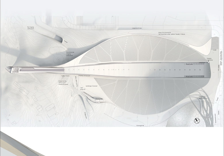
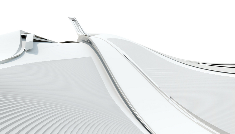
Excerpt of the competition jury: The proposal is characterised by an ”aerodynamic” design, where all the elements fit together in a unified, plastic form of great elegance. In design terms the proposal appears as the competitions most successful. It appears as a refined, highly developed design where the knoll building and the inrun flow into each other in one unified form.The result is a monumental ski arena that grows out of the landscape. The adopted architectural language is consistent and includes the design as a whole, from public flows, commentators boxes, judges towers and stands...
The proposal is one of very few based on asymmetrical spectator stands, where the southern stand extends further than the northern one and is situated lower than both the knoll and the stand on the opposite side...
The chosen solution can be attributed to the proposed wind protection, which is principally different from that which the programme sets the criteria for. Instead of solutions based on different types of screens or fabrics with an open, perforated structure, a permanent dense screening by a high concrete wall to the north is proposed. This is designed to function like a spoiler sending the air flow high enough over the outrun and further over the lower southern stands and judges towers to make the ski jumpers pass below the airflow. The wind technical specialists the jury has consulted warn against such a solution...
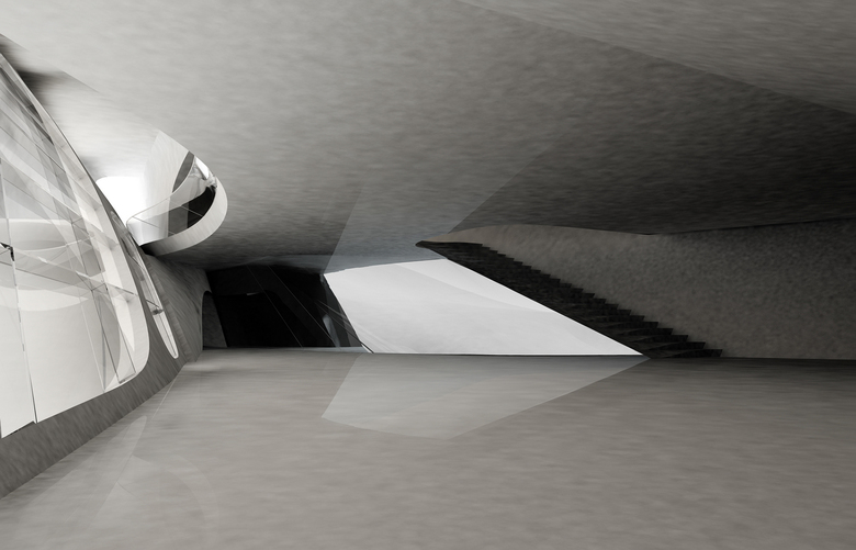
The proposal shows a large and in parts complicated knoll building, with a good plan solution, especially with regards to servicing the tourists inside. Unfortunately the tourists have not been given the same consideration with regards to the view from the square over the city and down the slope. The judges stands are given an excellent solution, elegantly integrated into the unified design of the slope...
In order to create a windstill situation along the jumping trajectory, two basically different strategies can be employed. The first strategy, as proposed by the competition organiser, uses semi-permeable wind sails in combination with wind breakers, positioned upstream, to slow down the wind around the jumping area.
A second strategy, as proposed here, uses the tribune to generate a large flow separation to guide the wind over the jumping area and create a wind-still backflow region in this area. The advantage of this strategy is that the jumpers always experience an upward wind direction with low wind speed. There is a large enough spoiler at the luv-side of the tribune. This backflow region ensures optimal jumping conditions. The results show that a spoiler of 3 m height is necessary to establish a well separated flow. The jumpers are safe from the large fluctuations stemming from flow reattachment. Wind direction throughout the whole upper part of the arena includin the complete jumping trajectory is upwards close to the ground. This is a result of three-dimensional effects leading to a twisting of wind direction between upper (separated) shear layer and the wind close to the ground. We observed very quiet wind situations along the whole jumping trajectory, the wind blowing at very low speed constantly upwards with nearly no side wind for the jumpers. This seems to establish optimal jumping conditions.
The main construction principle is to be a fully cantilevered tower in reinforced concrete utilising prestressed cables in the tension zone. The proposed integrated windshield is used as a structural element and helps minimize deformations in terms of bending, torsion, and twistbuckling. The knoll building is to be built on elastic foundation points. The construction of the tower will be carried out using free climbing formwork and avoids the use of scaffolding. The section of the tower which houses the cablecar will be the leading edge of the contruction with other structures of the tower following behind. Preliminarary calculations give a concrete wall thickness which diminishes with the height of the tower from 50 to 20 cm.
- Architects
- LAAC
- Year
- 2007
- Wettbewerb
- (offen) 2.Preis
- Entwurf
- Kathrin Aste, Frank Ludin, Thomas Feuerstein, Andreas Hörl
- Projektpartner
- Snohetta, Oslo
- Konsulenten
- Statik: aste weissteiner zt-gmbh, Innsbruck, Hydromechanik: Prof. Dr.-Ing. habil. Michael Manhart


